21). Painting the engine bay

As usual, I was working on things out of the order they should be done in. Like painting the engine bay. I had planned on painting it prior to applying the undercoating, swear… But I wanted a particular flat black that I was having a hard time finding. That, combined with impatience, meant I painted the engine bay last.

Here it is after the first light coat of flat black was applied.

The paint I ended up using was an aerosol flat that probably cost more than it should have, but went on really nicely, almost like using a paint gun. Dried super quickly too, only drawback was, it took several coats to cover properly.

Most importantly though, it turned out the way I wanted it to.

I still need to give it a coat of automotive flat clear, but I was happy with how it looked.

Now on to the fun part, rebuilding the suspension.


To find a particular page, use the search feature or index page.


20). Inner fender fabrication

Since I had gotten ahead of myself with the undercoating, I still needed to complete some fabrication on the front bumper and hood attachment locations on the inner fender. So I cut out the rusted portions and welded in new steel. I ended up having to do both sides.

First the passengers side…

Then the drivers side.

Once I had both sides taken care of, I needed to recreate the angled bumper support bracket as the original was beyond saving. I fabricated these out of 14 gauge and reused the nuts from the original bracket.

Then I welded them onto the inner wing and coated the entire lot in seam sealer. I get a little carried away with the seam sealer sometimes.

After that was all said and done, I painted on a couple layers of undercoating and was happy with the outcome. Even if it is a bit hard to see what’s going on in the picture below.

I’m aware that the car doesn’t have undercoating applied past the end of the front fender, where the headlight bucket starts. But for the sake of consistency, I decided to take it all the way to the nose of the car. Should’t hurt, and in my mind, it may help add another layer of rust prevention.


To find a particular page, use the search feature or index page.


19). Front undercoating

I’m probably making more work than necessary for myself, but before I applied undercoating to the bottom of the car, I added a little body filler in a couple spots that my fabrication skills weren’t quite up to par.

After that had been sorted, I began mixing up some undercoating that was originally intended to be a truck bed liner and began to apply it to the underside of the car.

Here’s what I learned from this experience. One, you can apply it in much colder temperatures than the instructions claim and it’ll adhere just fine.

Two, it really does take two coats to get adequate coverage. And three, it turned out better than expected.

Oh and four, I can be a real impatient bastard. Wait, I already knew that. As you can tell I hadn’t finished all of the fabrication yet, because like I said, impatience.


To find a particular page, use the search feature or index page.


18). Frame rail support

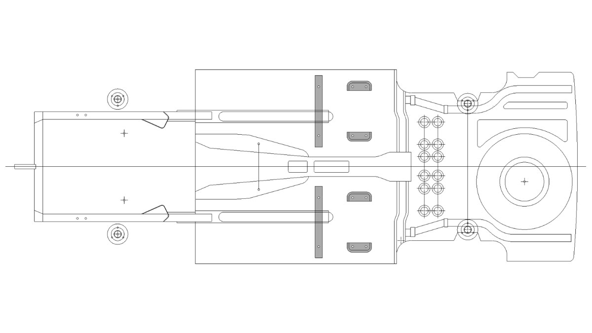
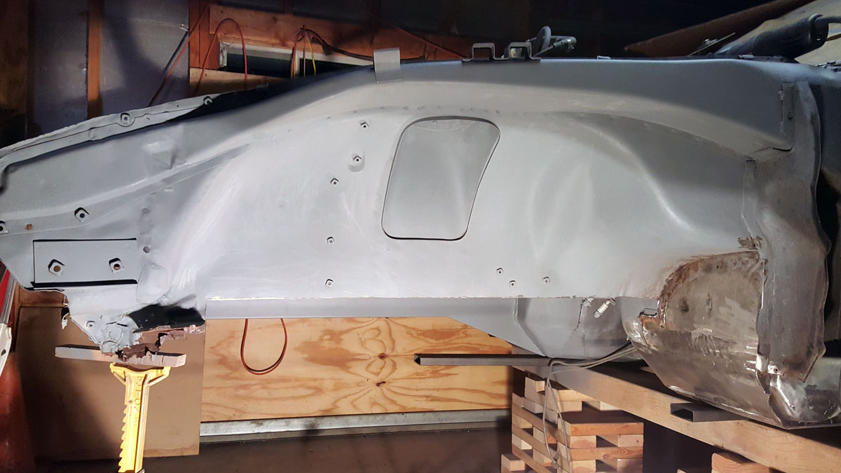
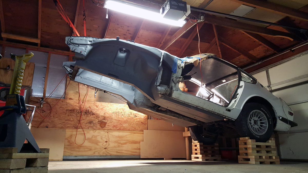
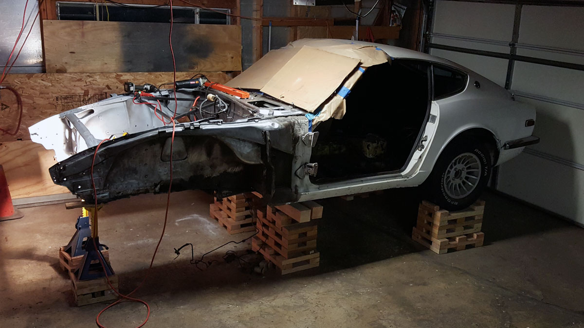
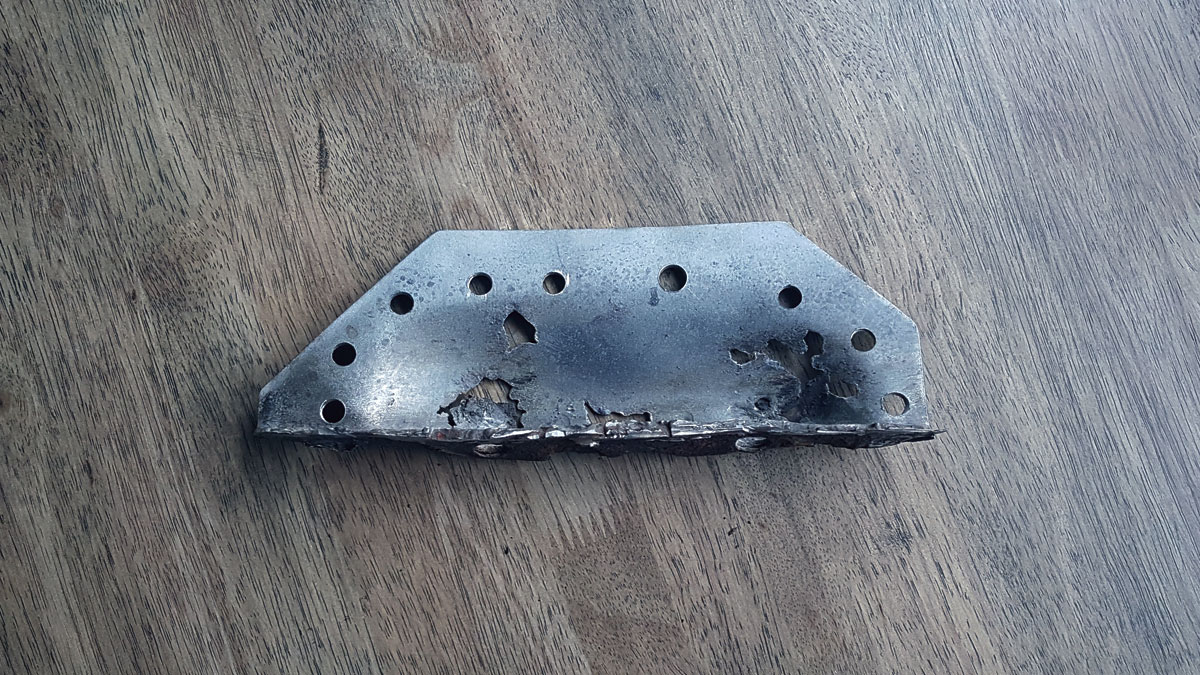
As most are aware, the 240 leaves the factory with a uni body construction and frame rails that don’t run the entire length of the car. They have frame supports that only go about two thirds of the way back.

Given the choice to replace these short frame supports with full length ones, I took it. Figuring it would help with overall rigidity, give me options down the road if I chose to do more with the car and honestly, just because it seems to make more sense.

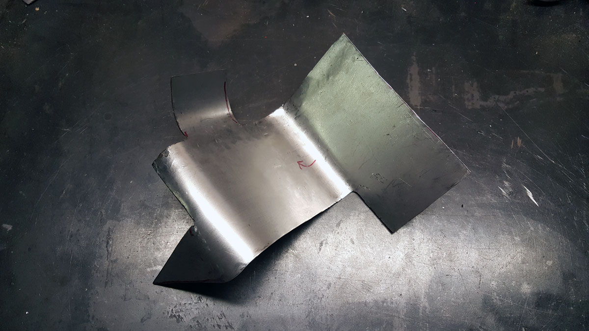
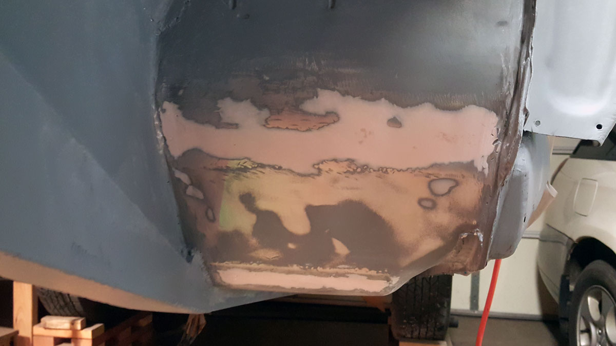
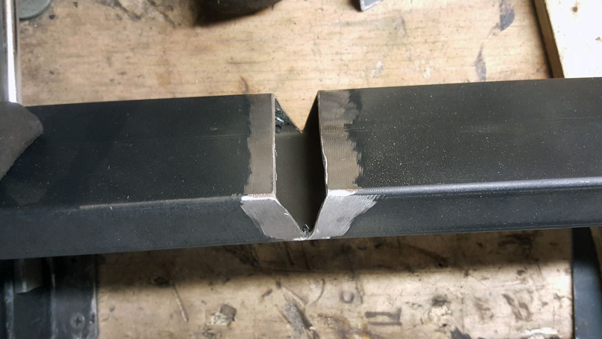
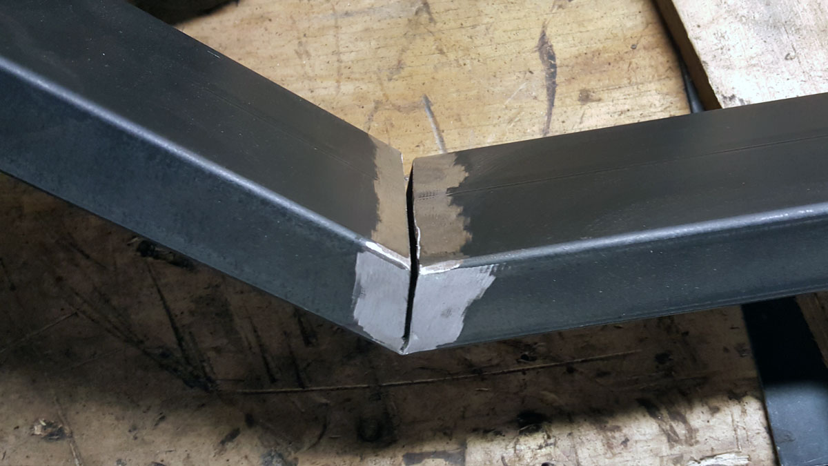
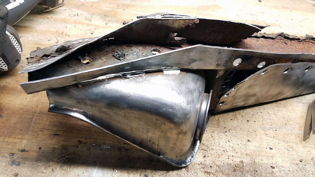
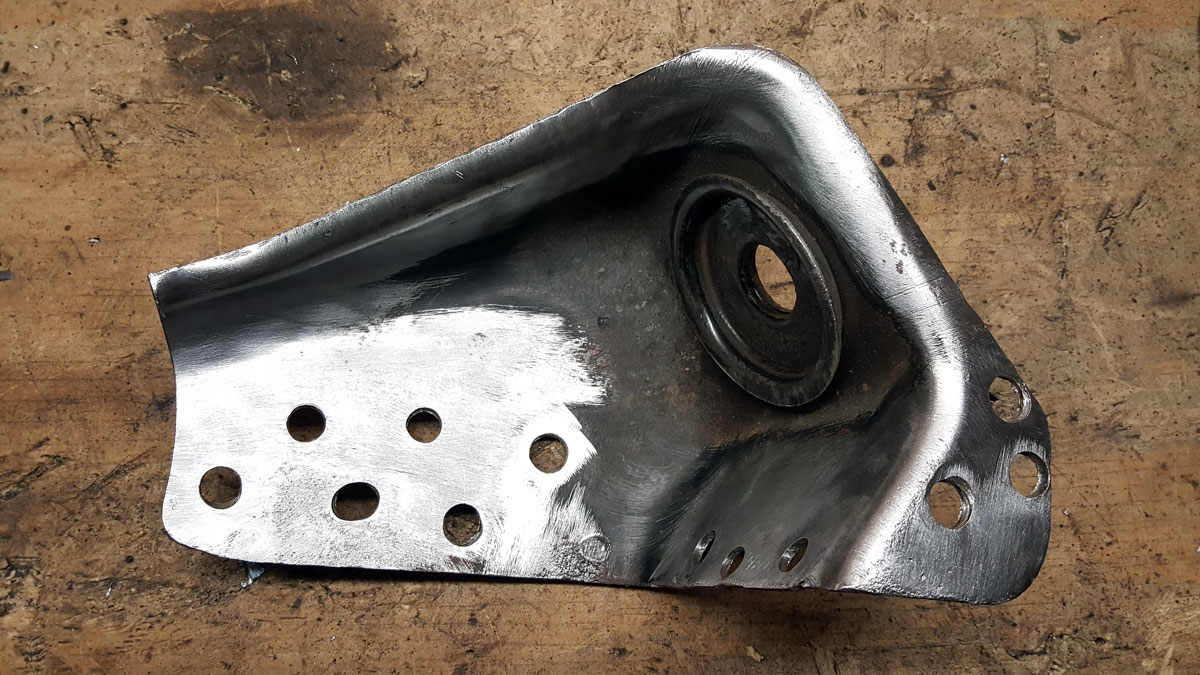
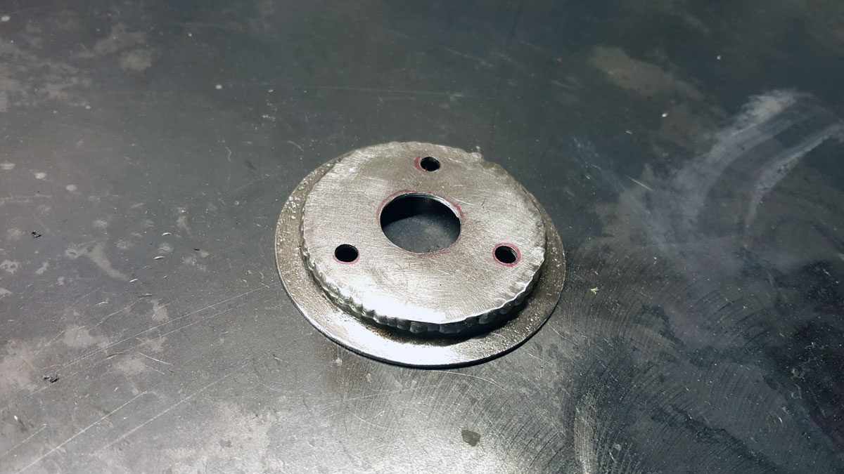
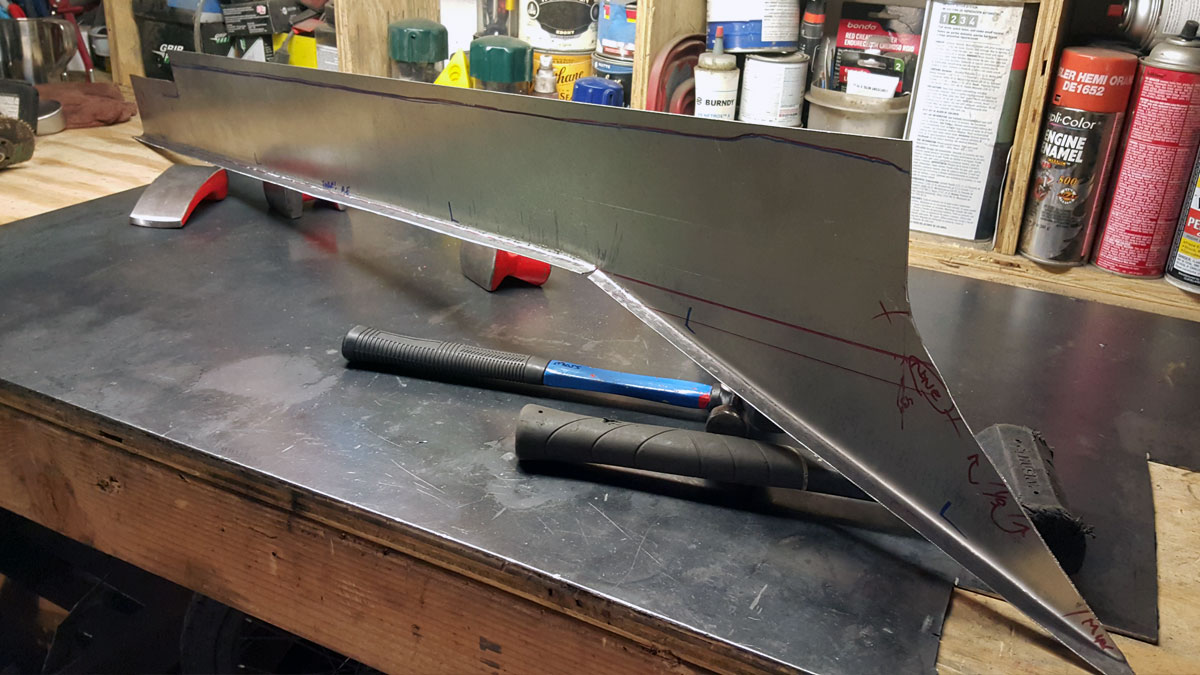
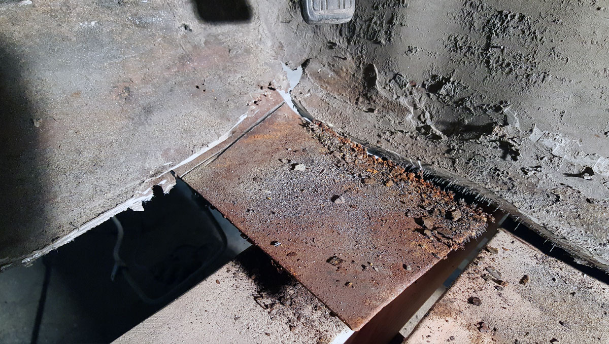
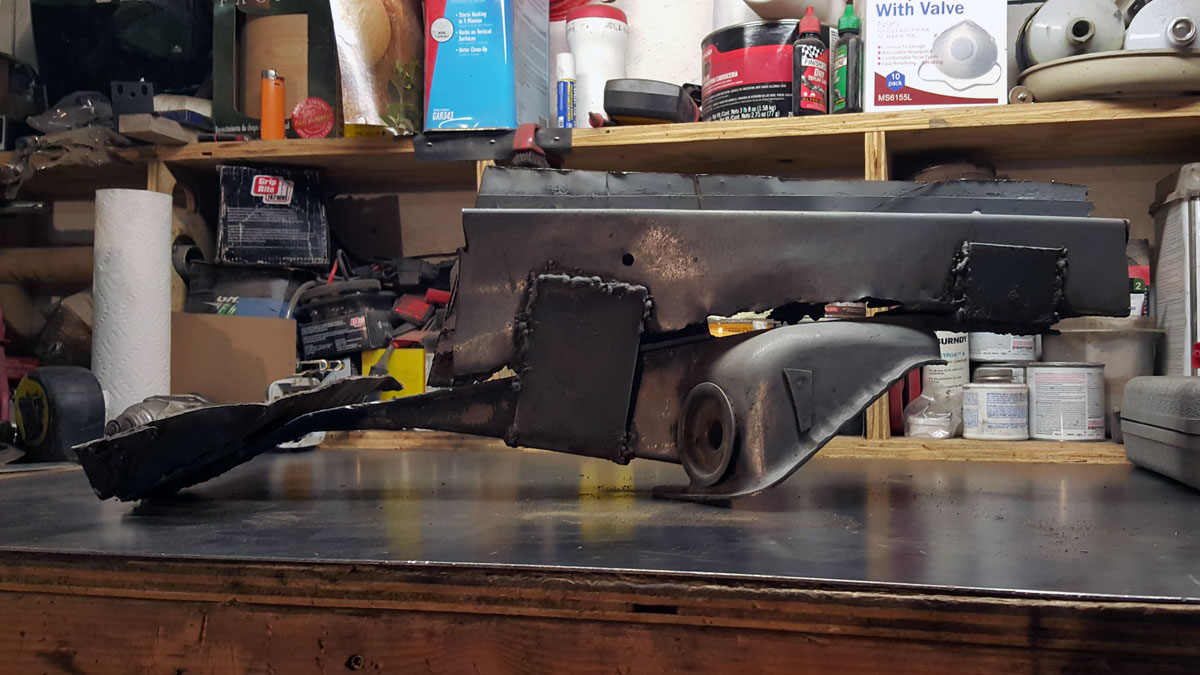
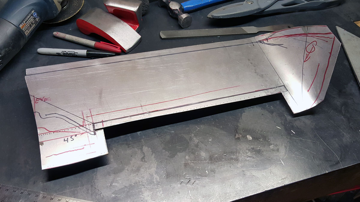
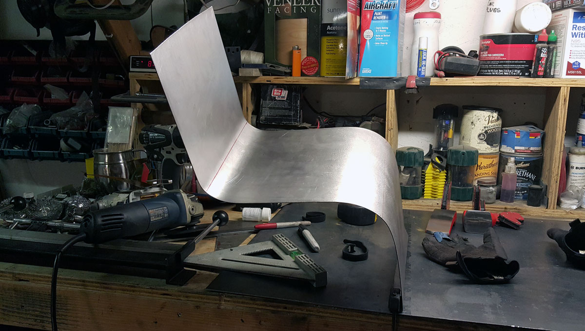
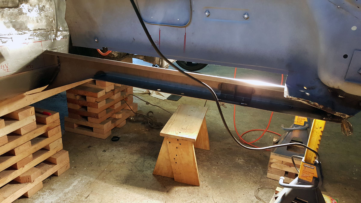
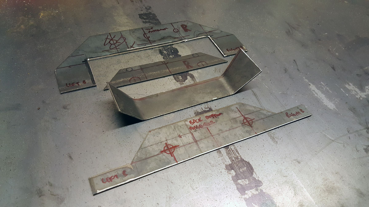
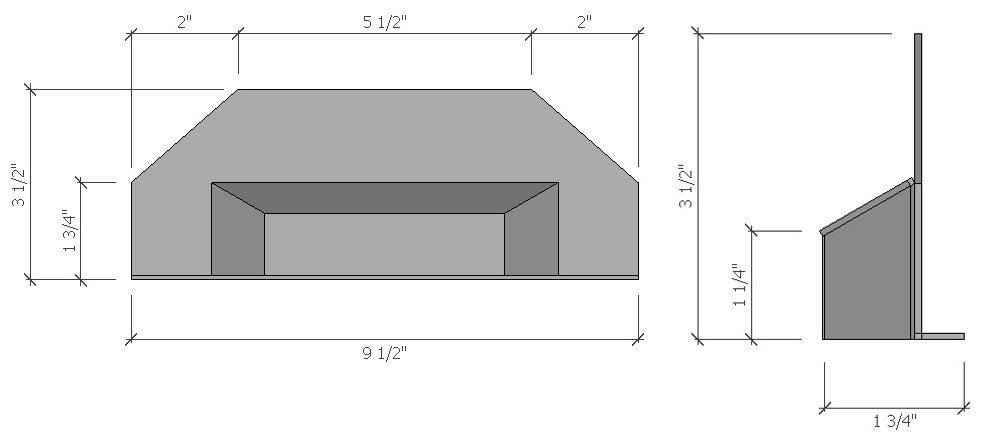
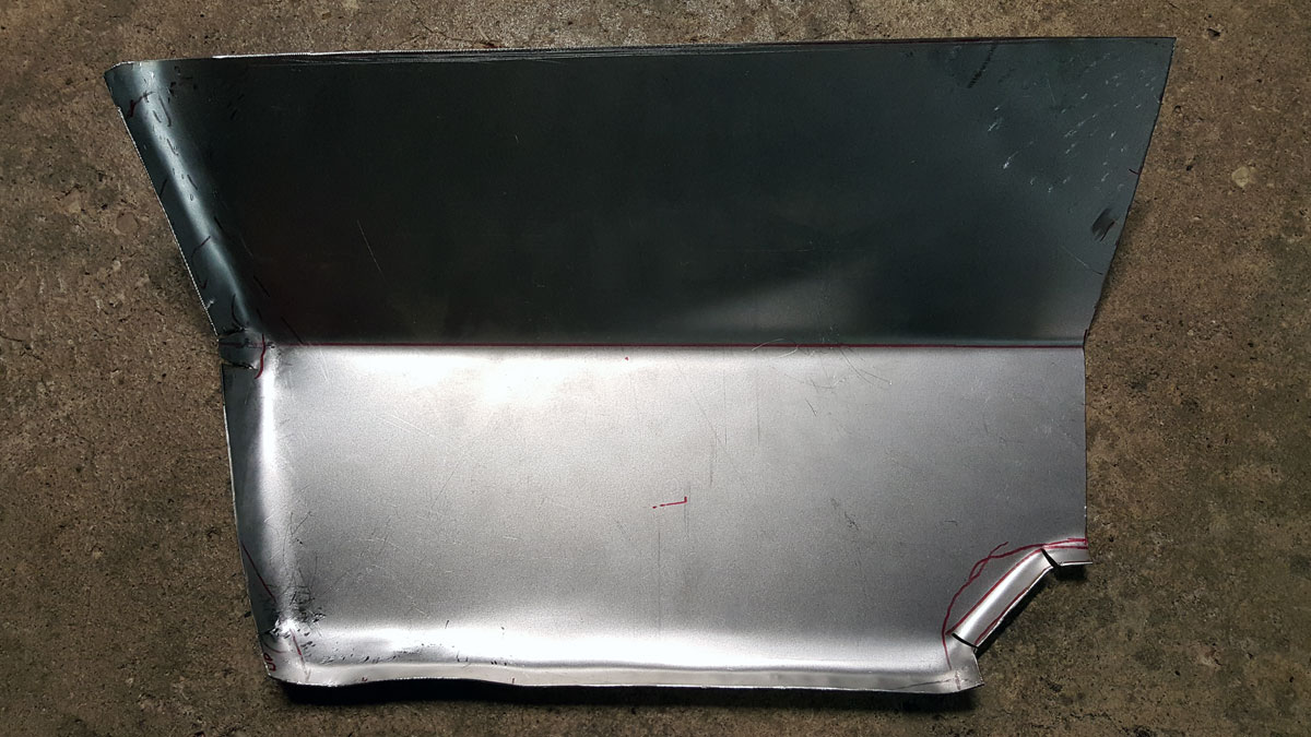
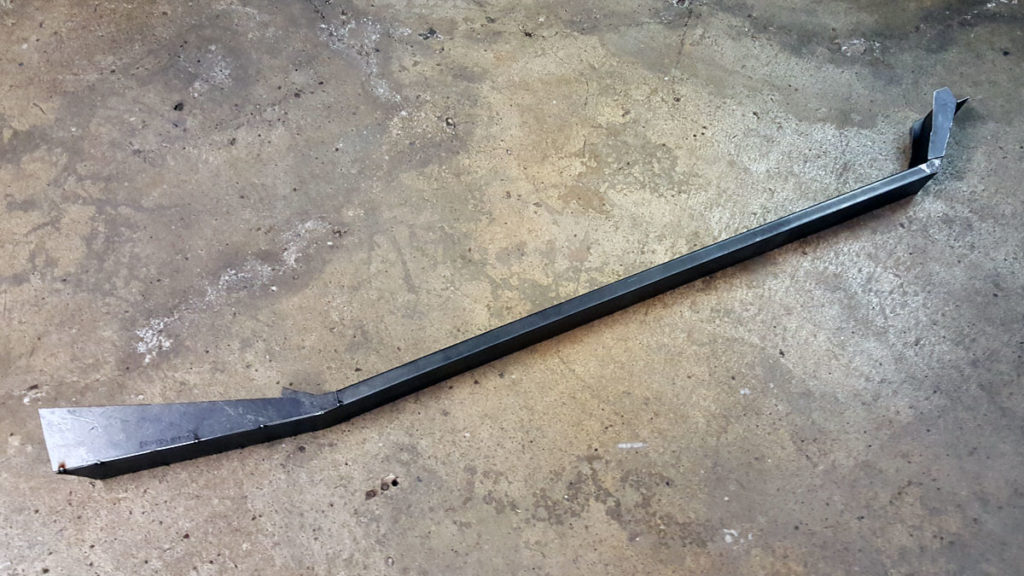
So I began by taking a piece of 1×3 tube steel and cut a notch out of one side so I could bend the tube and weld it to the desired angle. I did this to both ends.

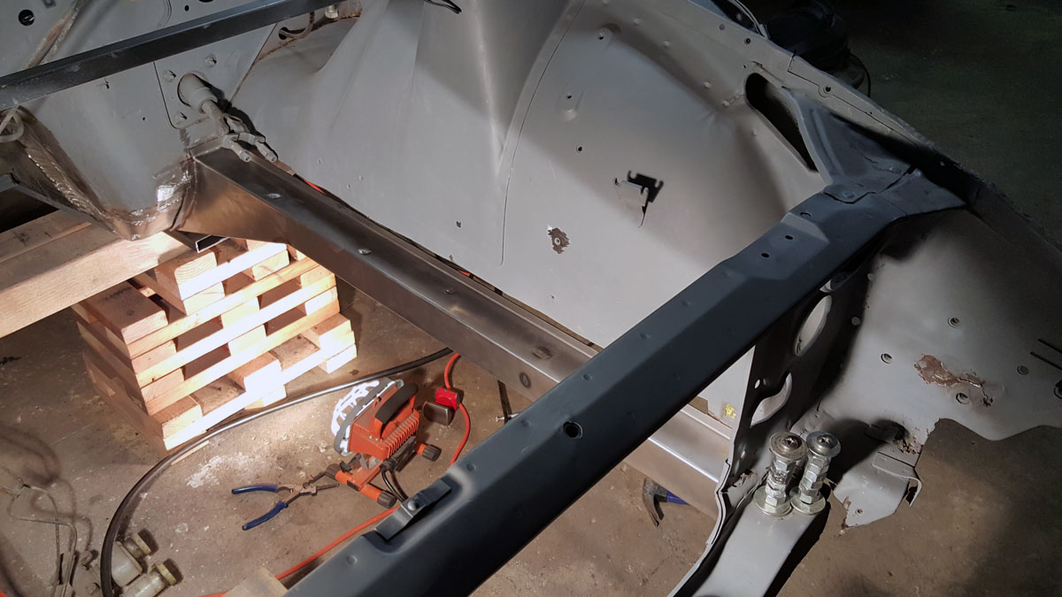
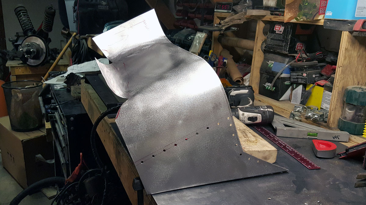
I fit it to the car a few times, cut some 14 gauge to bridge the gaps between the tube and the car and tacked it all together.

This was also around this time I tried to cut my thumb off with an angle grinder… Good times. Had I not been wearing leather gloves, I might have succeed.

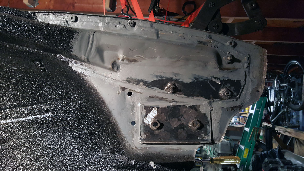
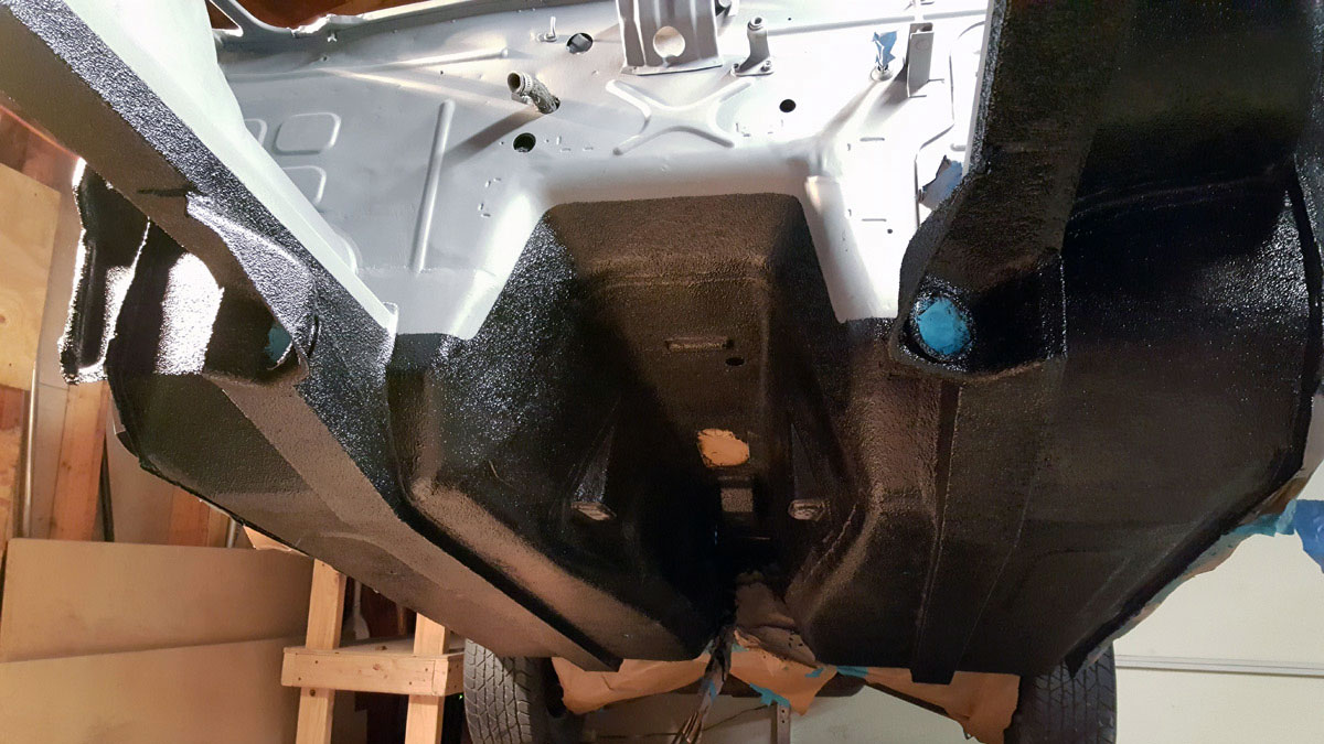
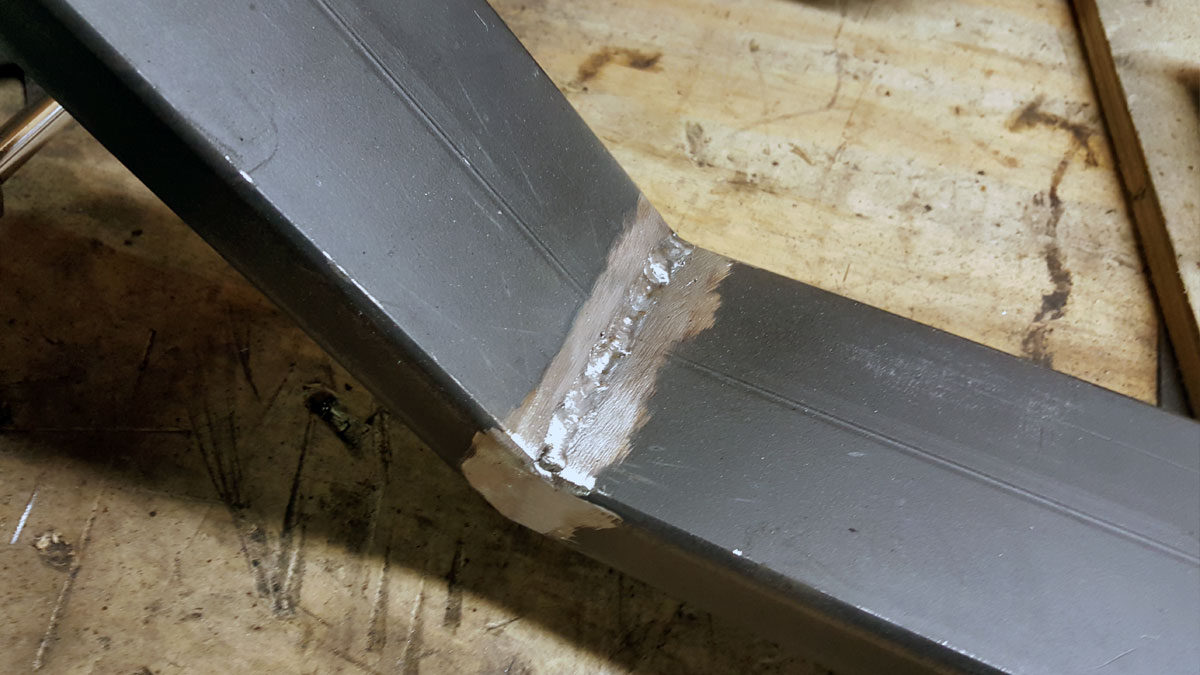
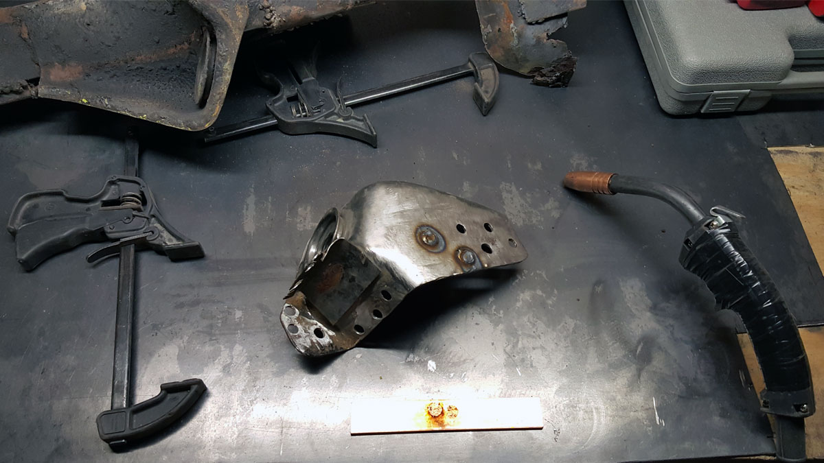
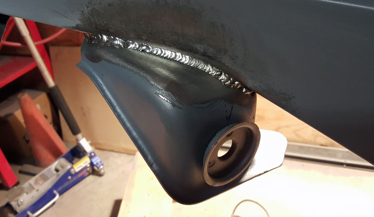
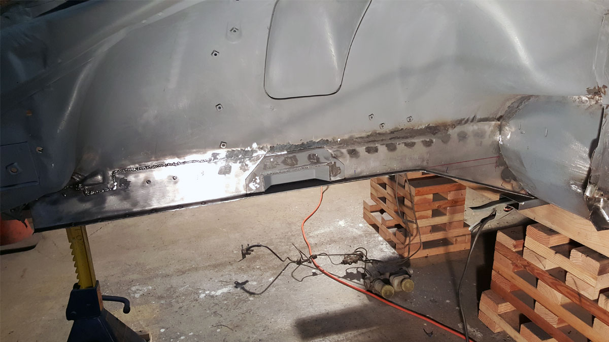
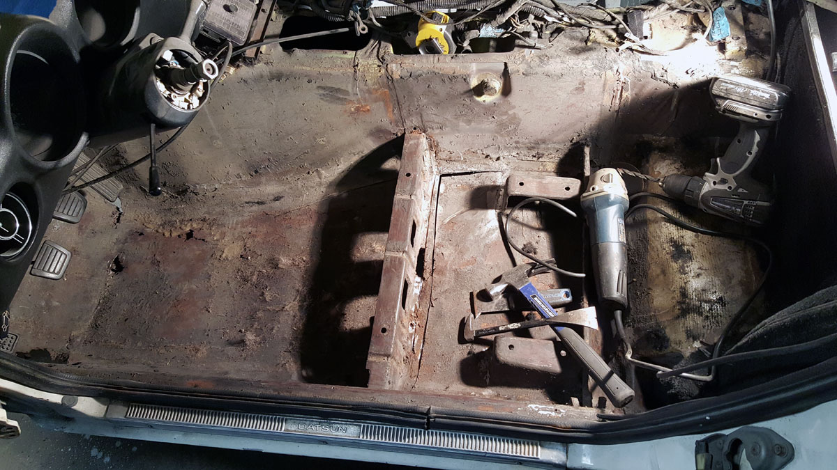
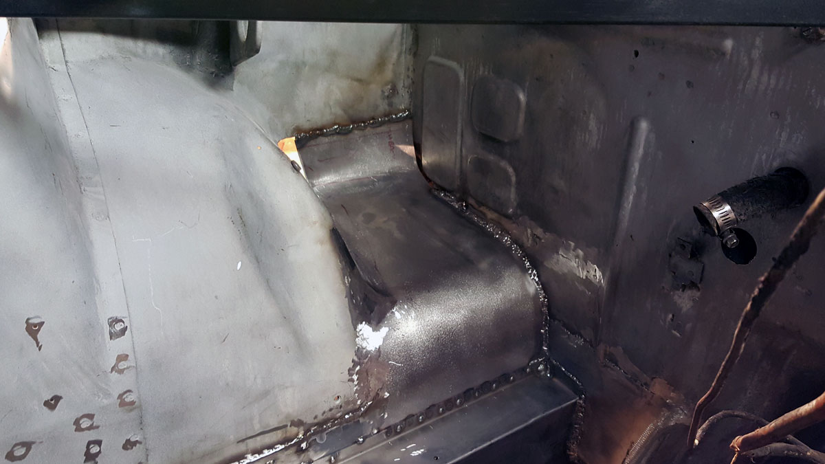
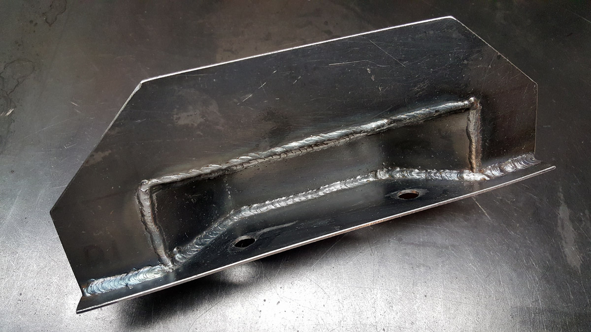
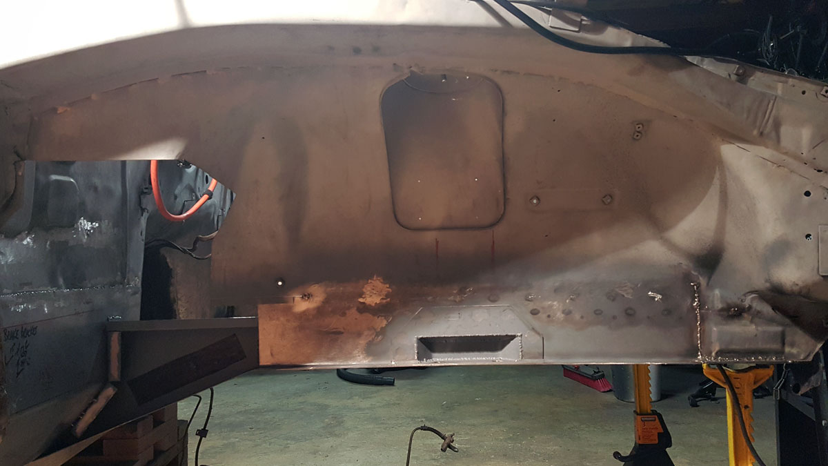
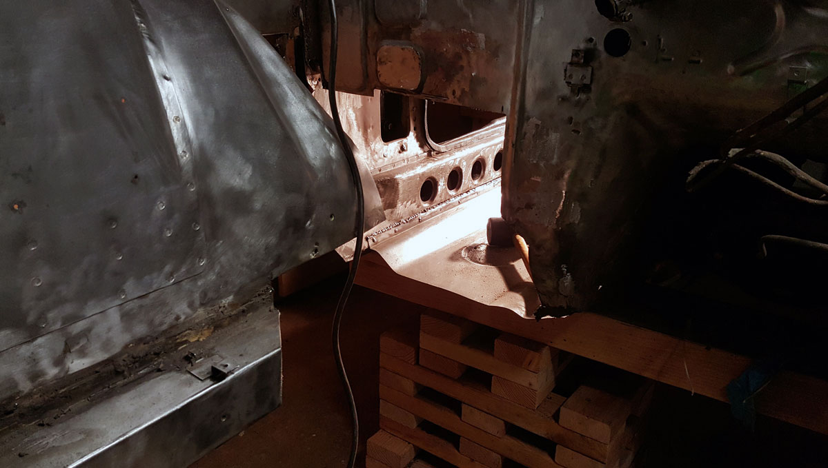
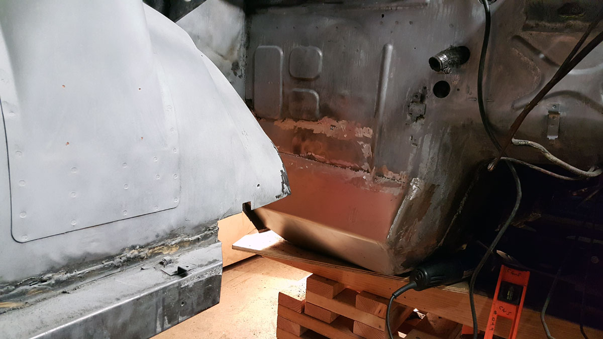
After I patched myself up, I welded together the tacked frame supports, then welded them to the underside of the car.

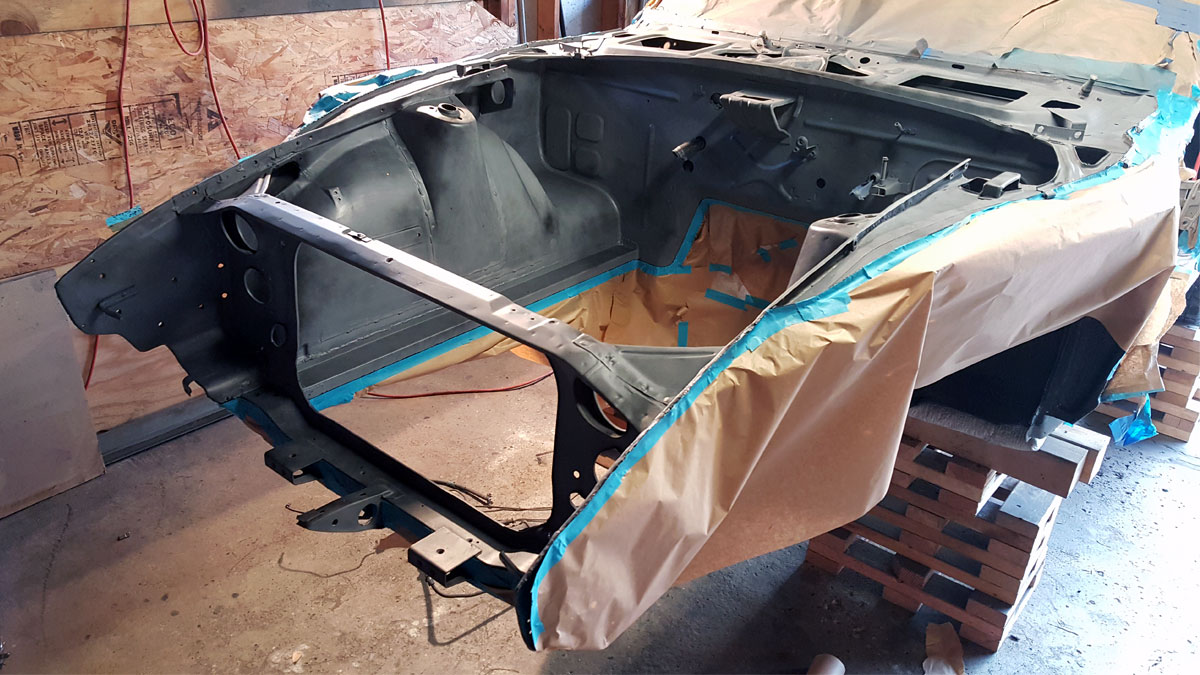
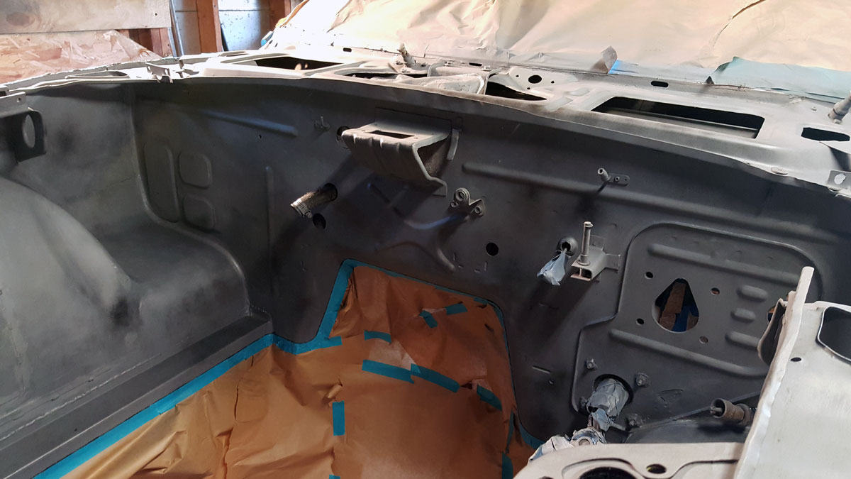
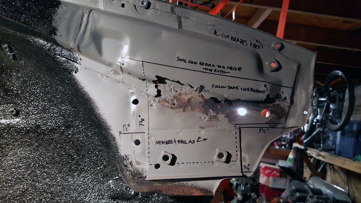
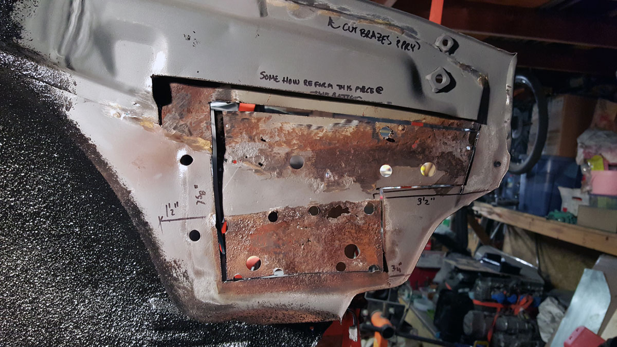
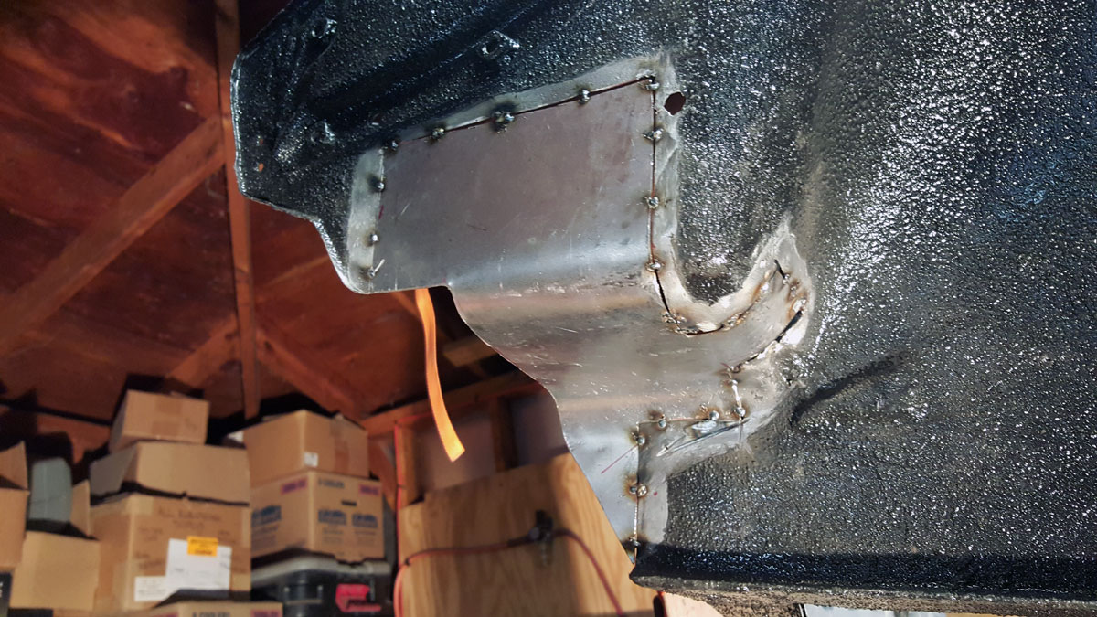
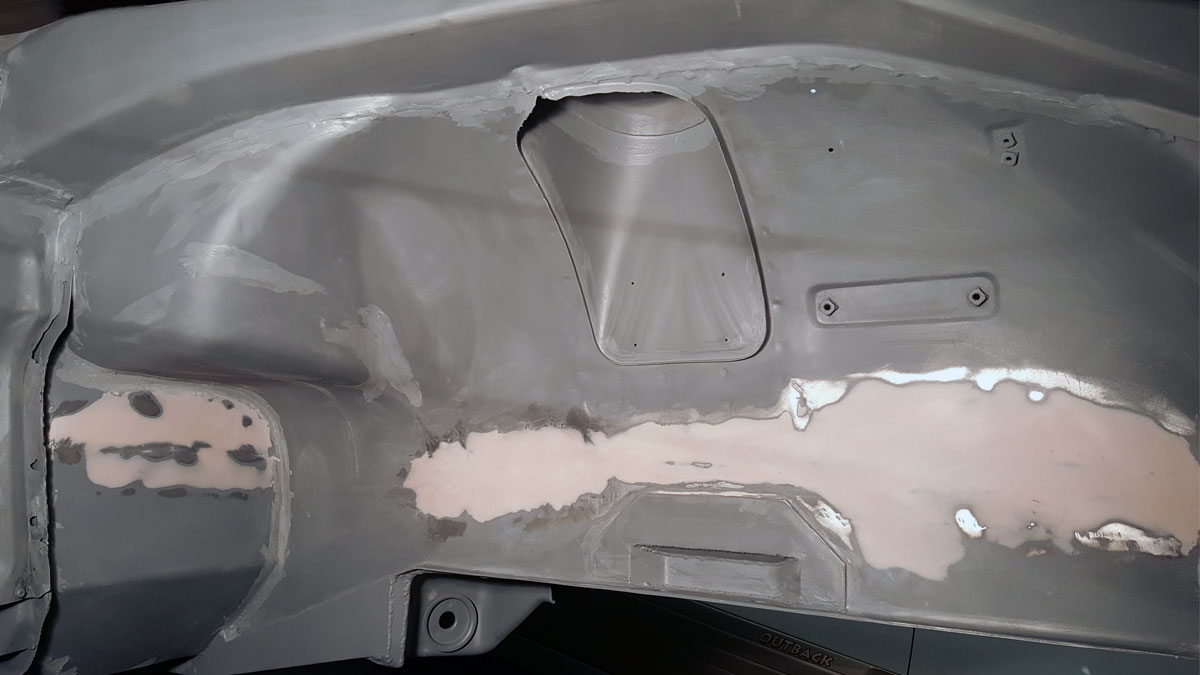
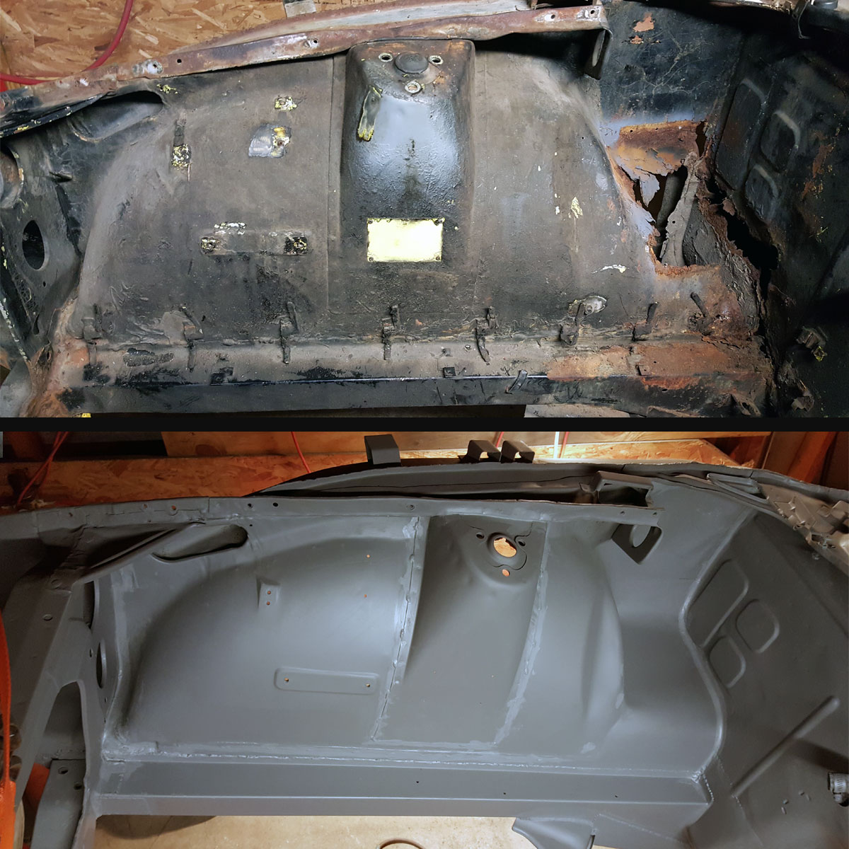
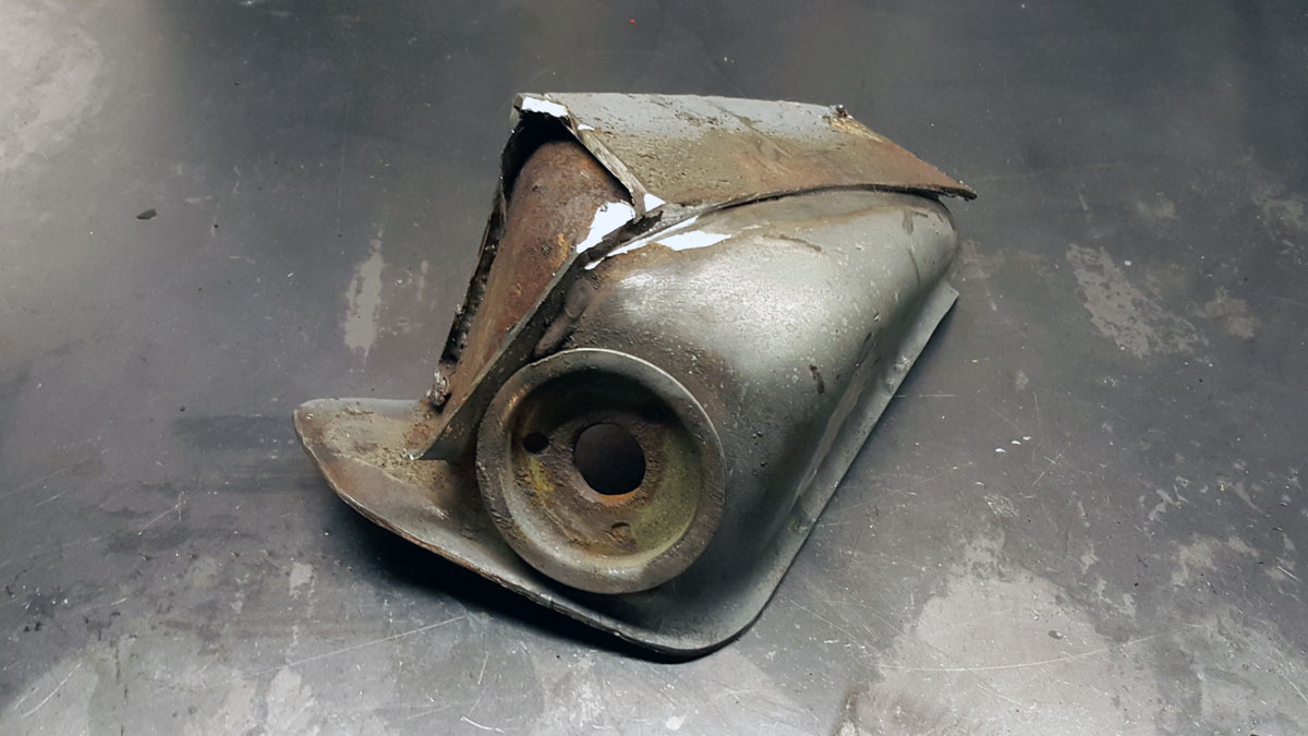
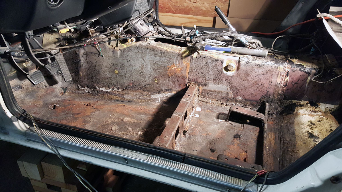
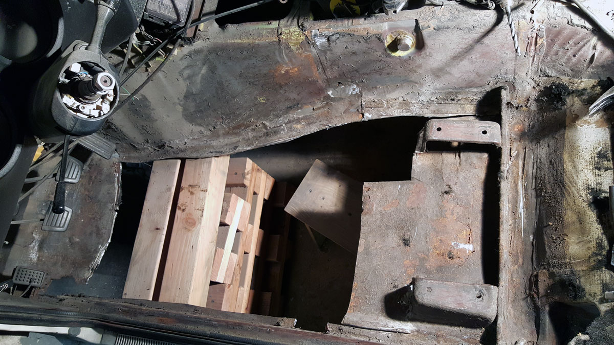
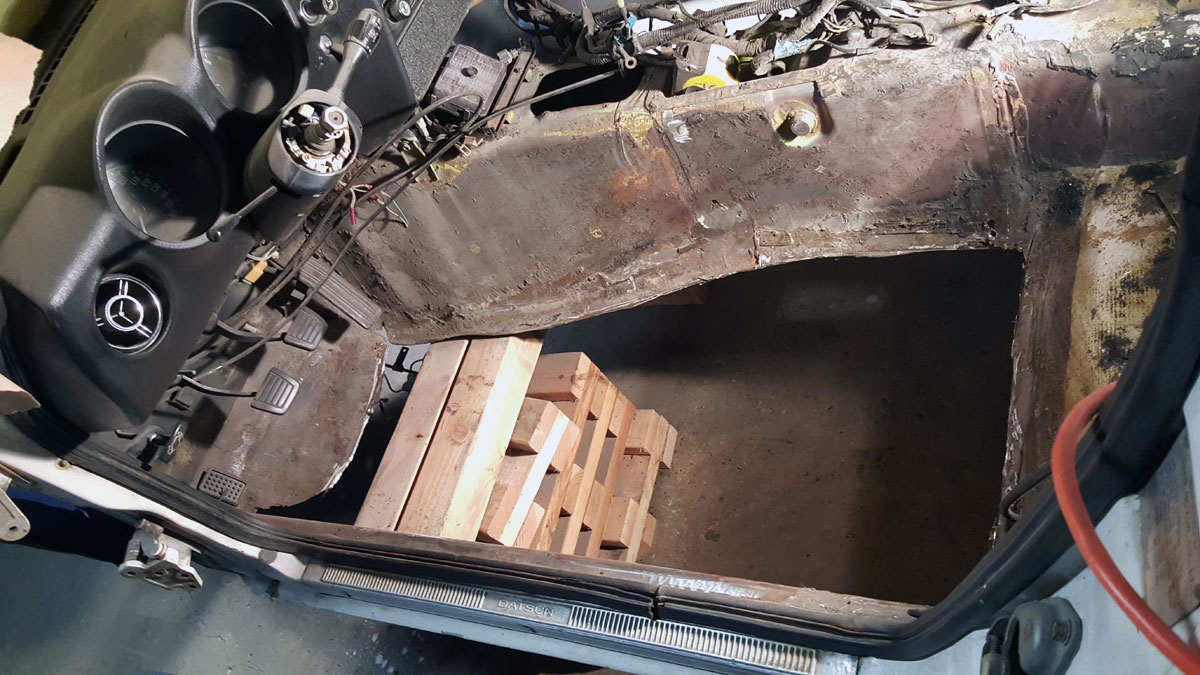
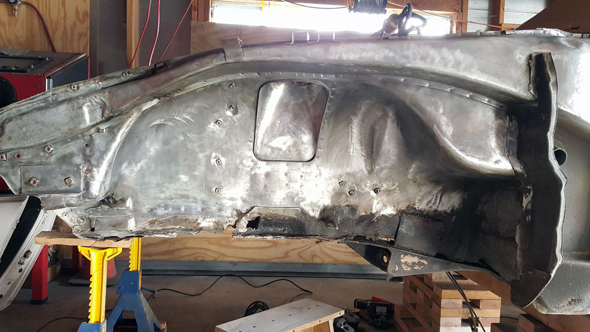
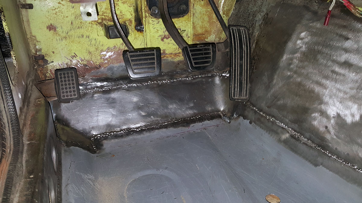
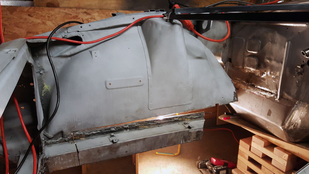
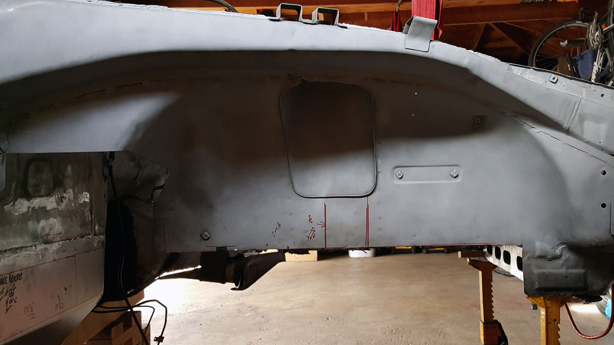
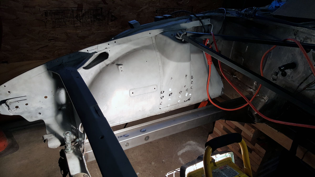
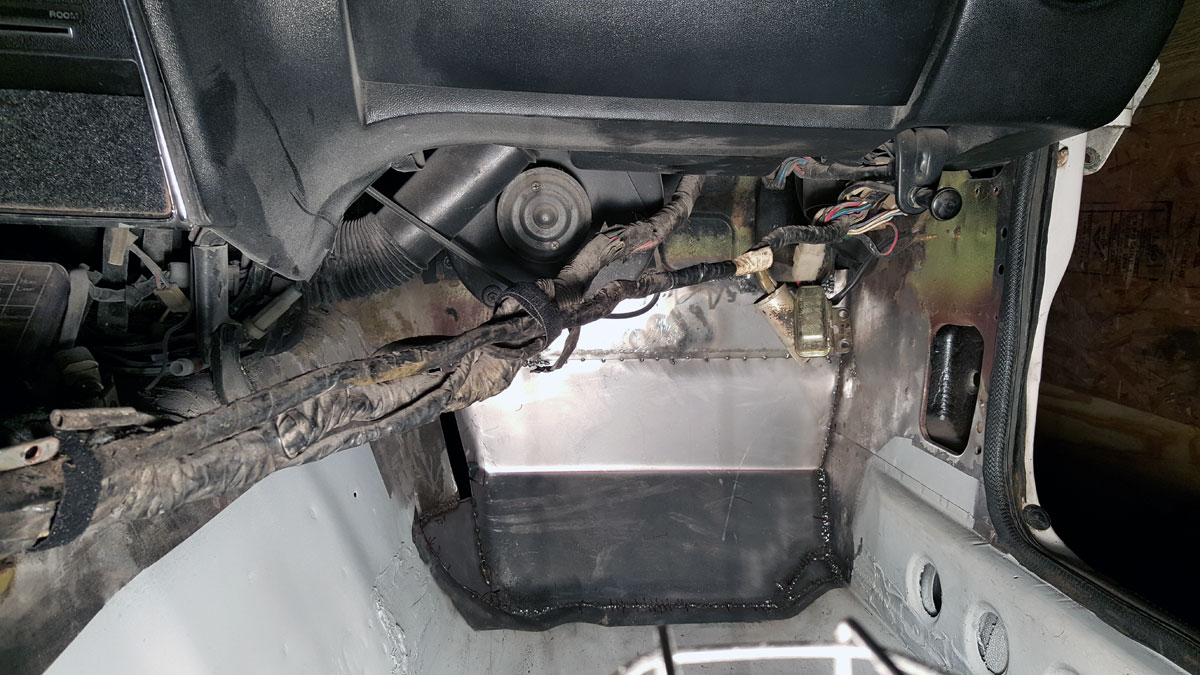
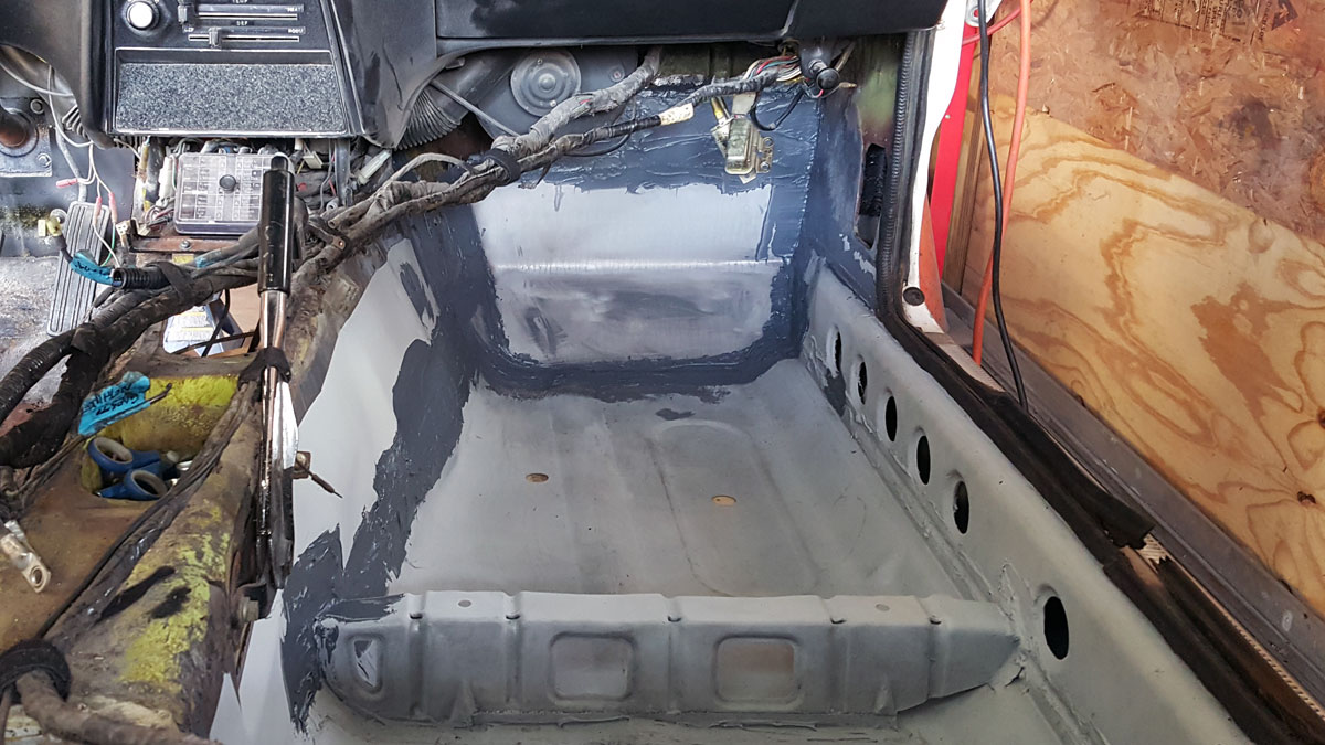
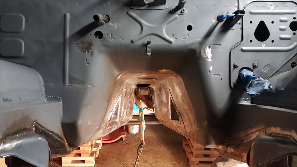
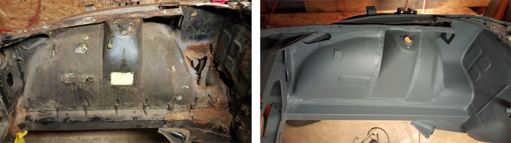
After I had attached the frame rail supports, I moved on to the transmission tunnel. Cleaning it, like the rest of the bottom of the car, was no picnic. Media blaster or rotisserie or both is on the menu for the next project.

I was having a hell of a time removing the brake and fuel lines without removing the rear suspension too, which is why they’re wrapped  up out of the way, below the car.

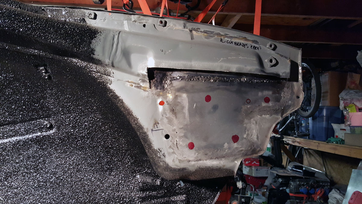
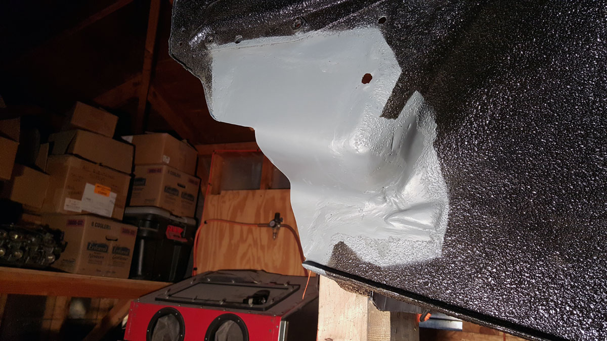
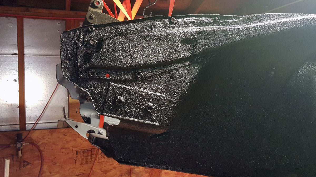
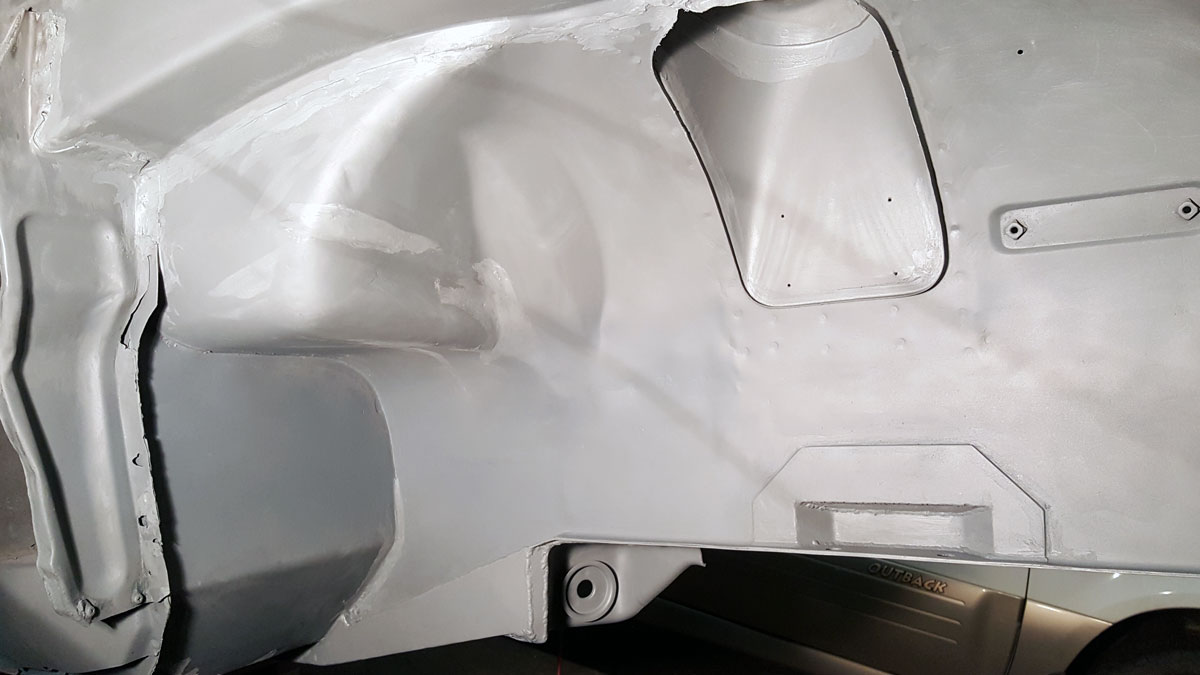
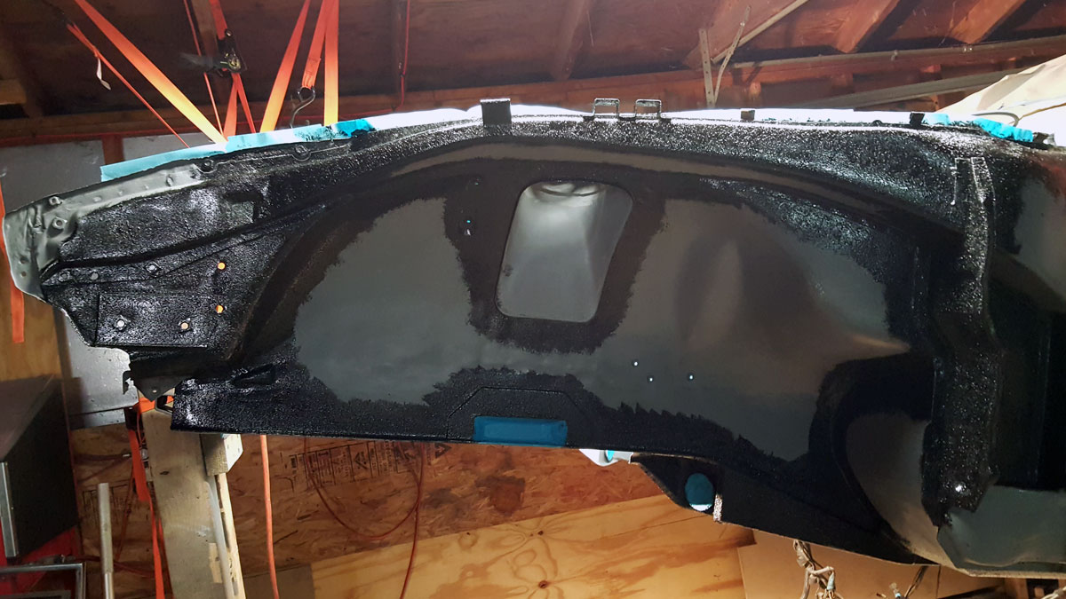
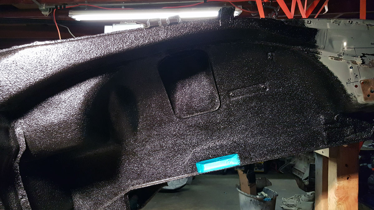
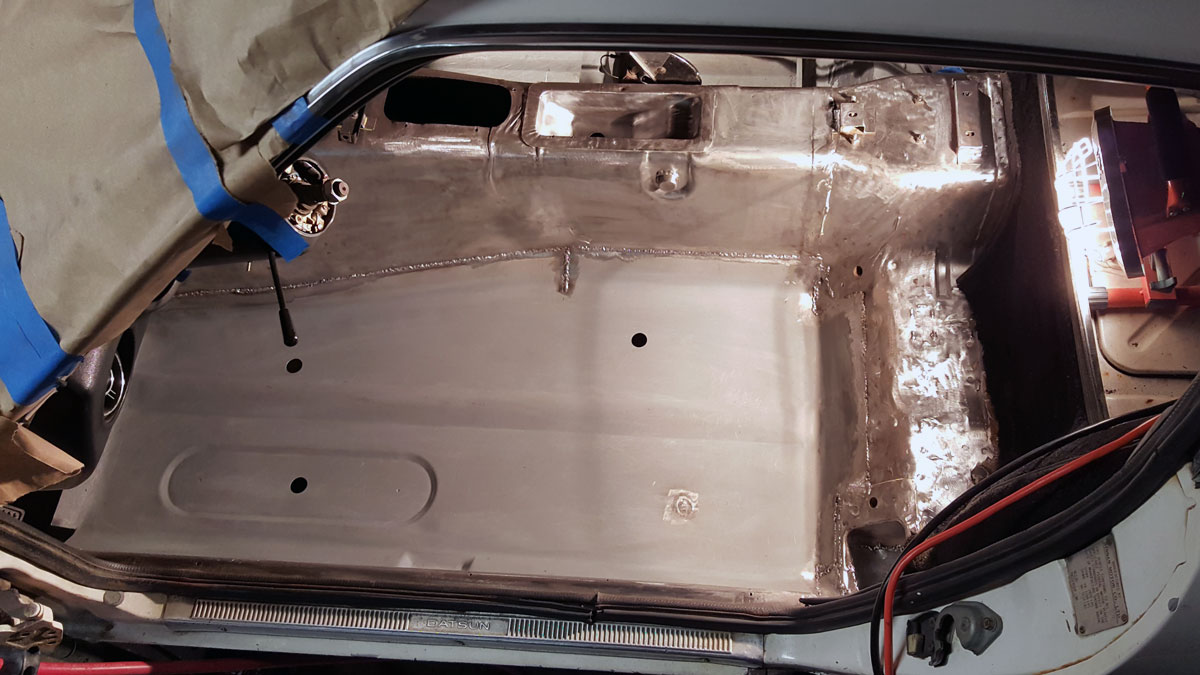
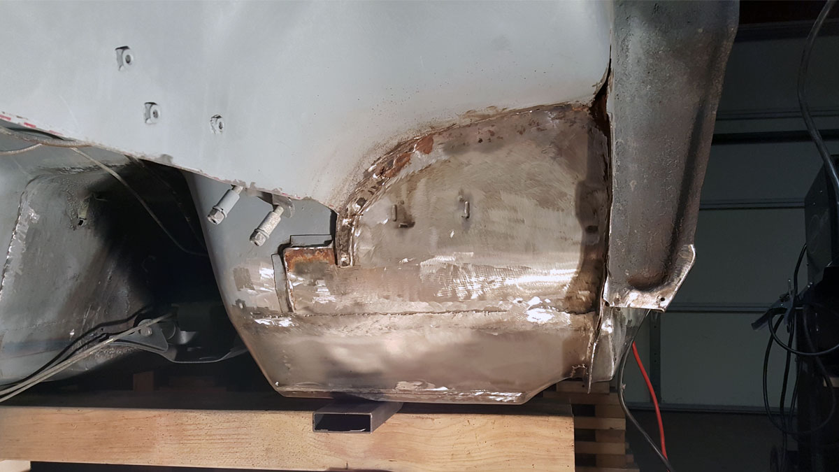
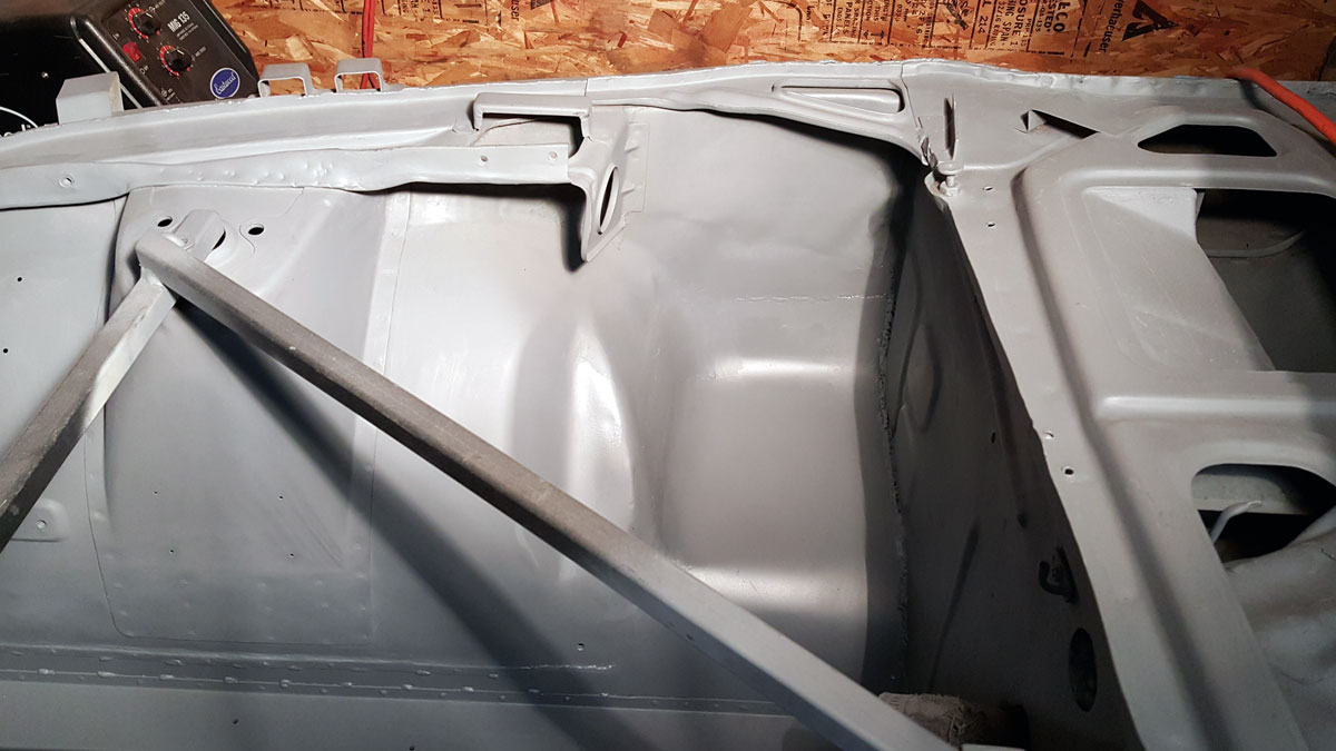
With the bottom of the car pretty much taken care of up to the rear axle, I epoxy primed then seam sealed all the joints. Using a caulk style seam sealer was the right choice. This also made me think of a saying I just read that I thought was so fitting, I stole it from @barra260z.

Remember,  a grinder and paint will make you the welder you ain’t.

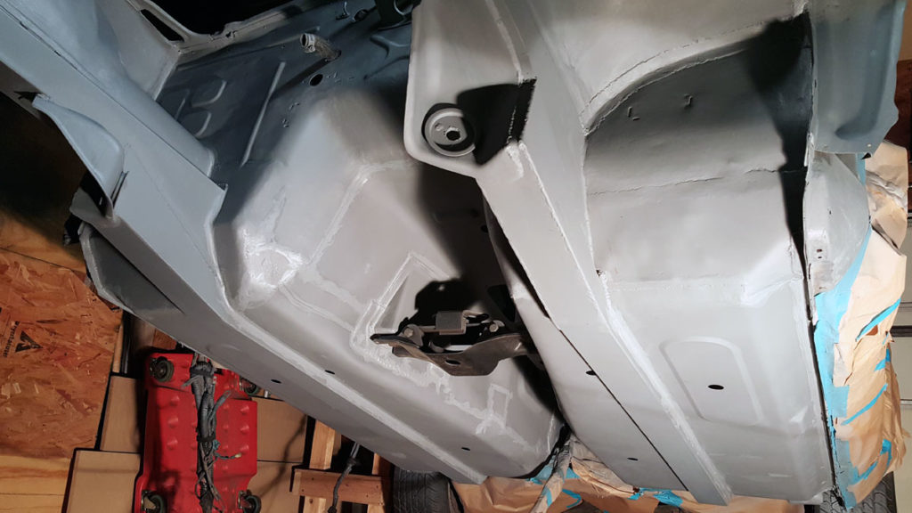
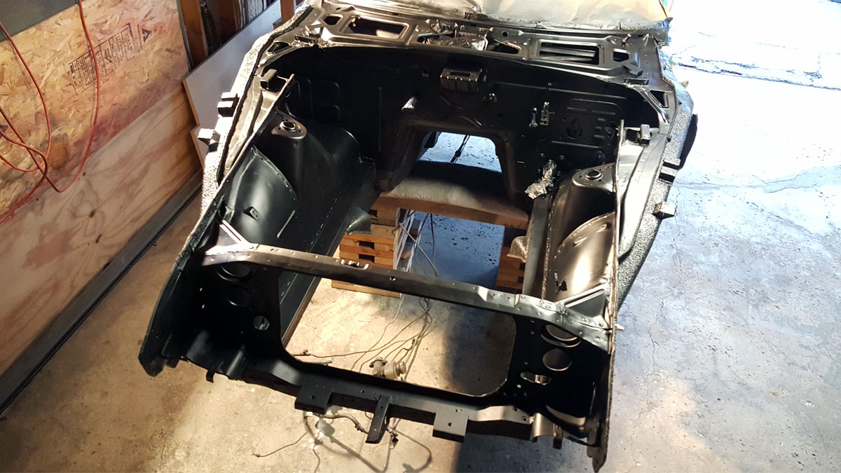
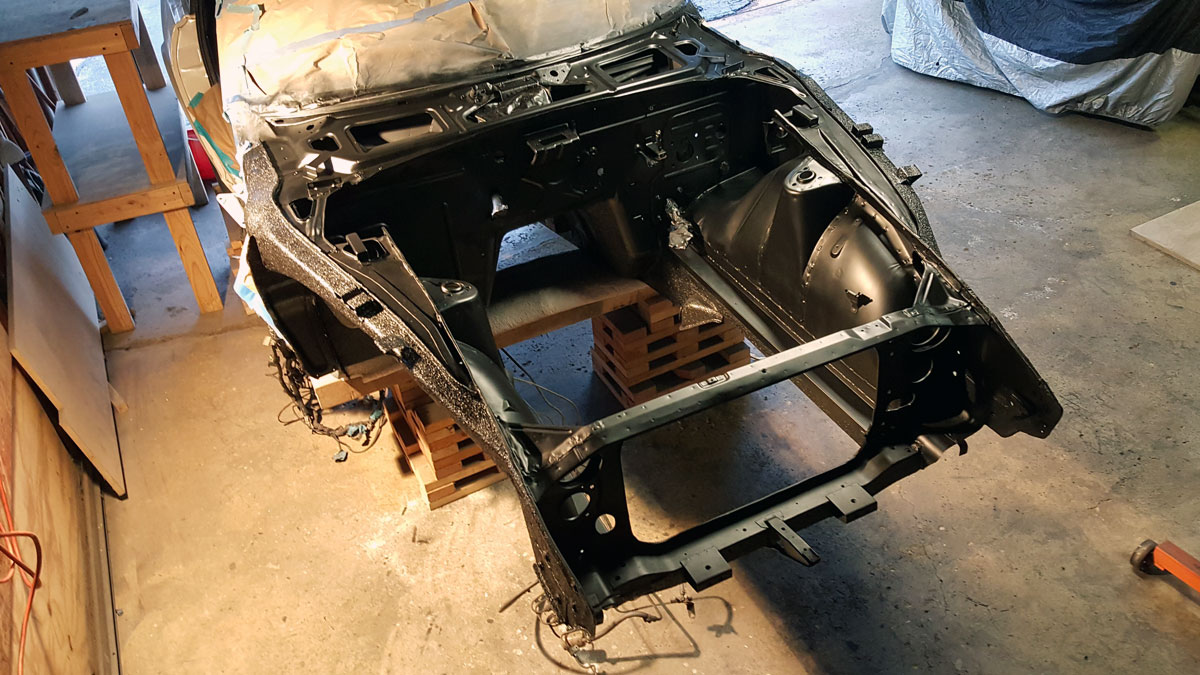
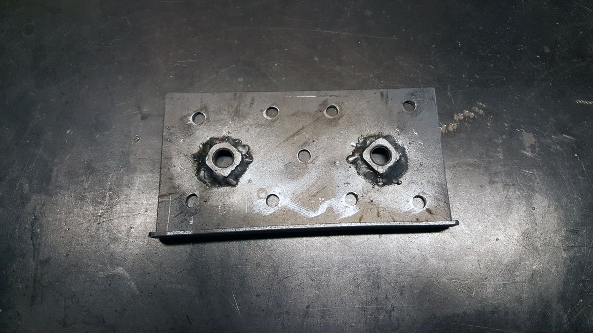
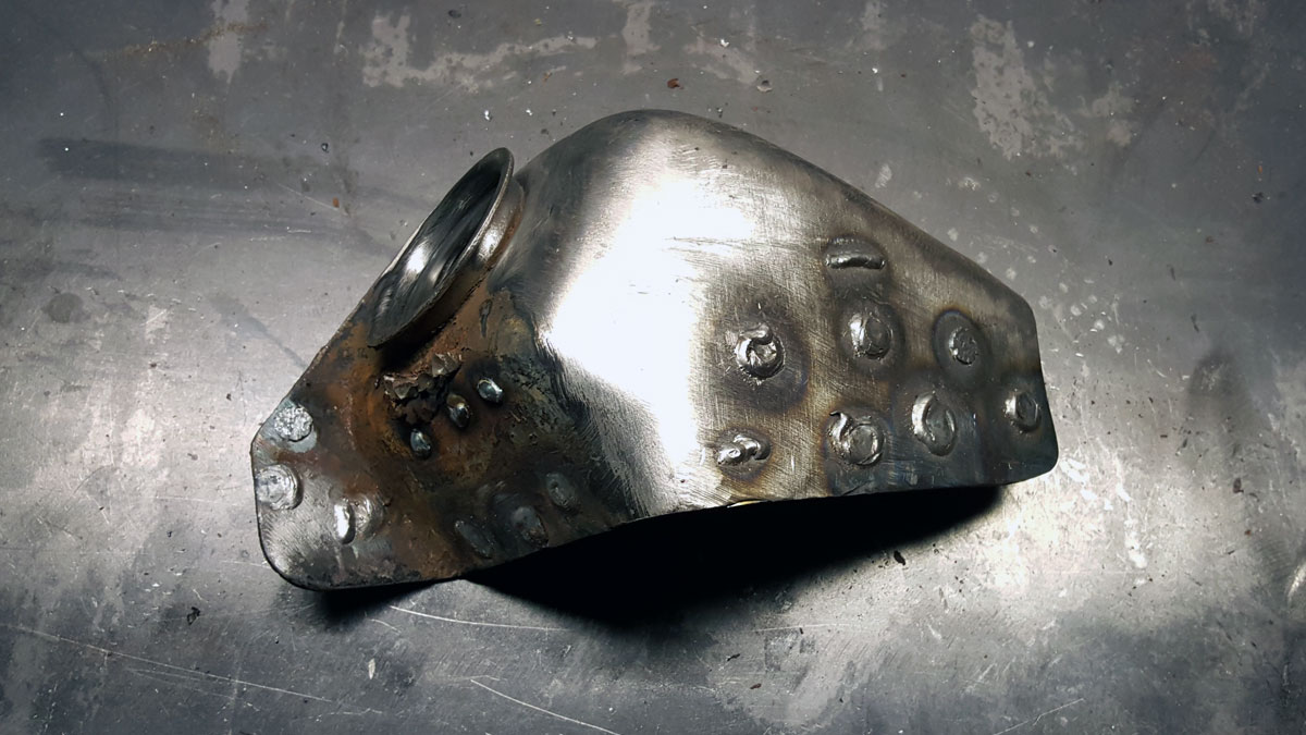
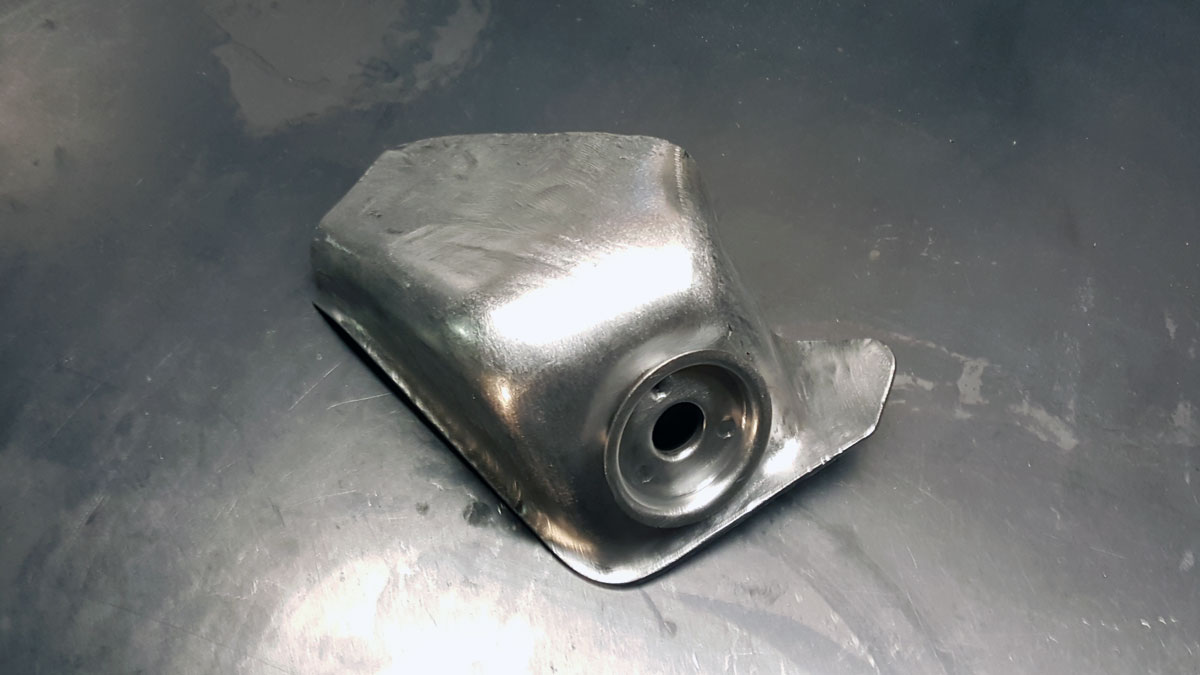
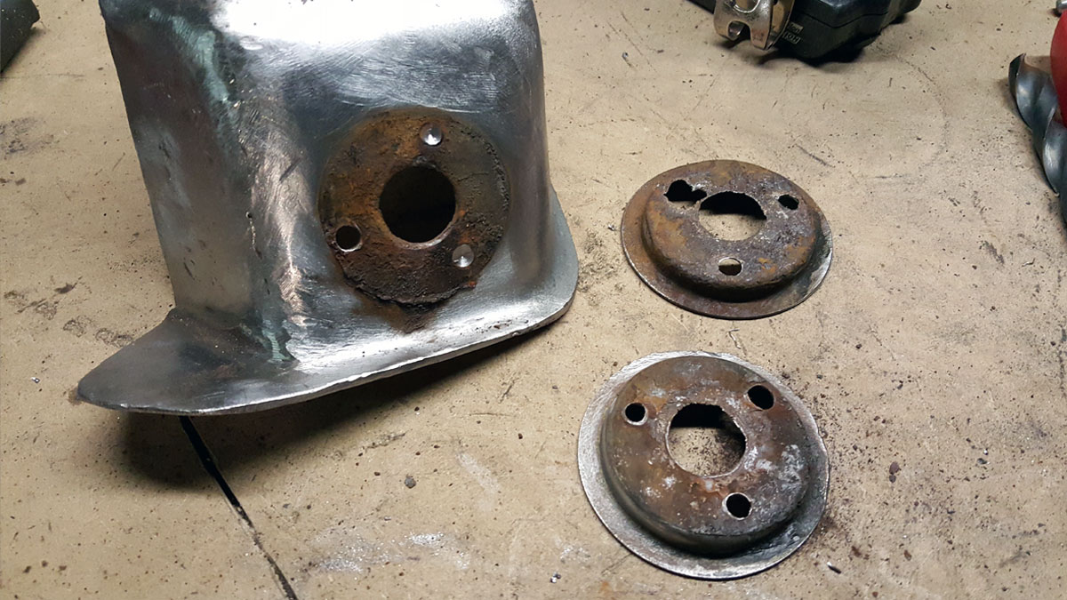
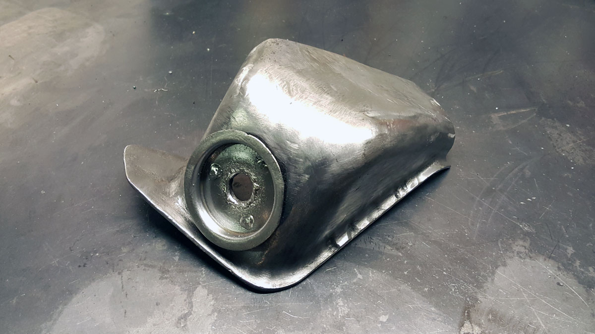
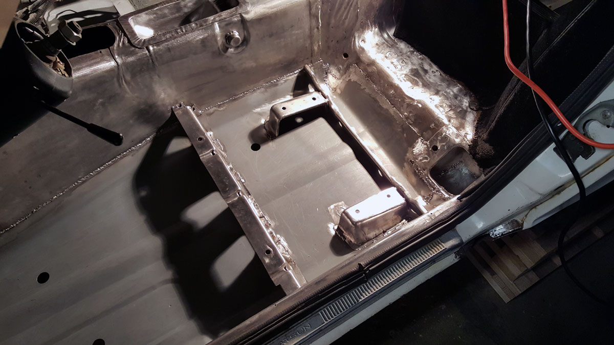
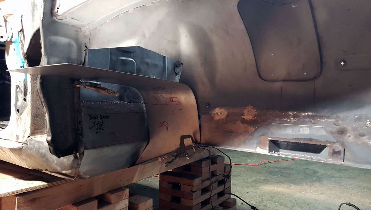
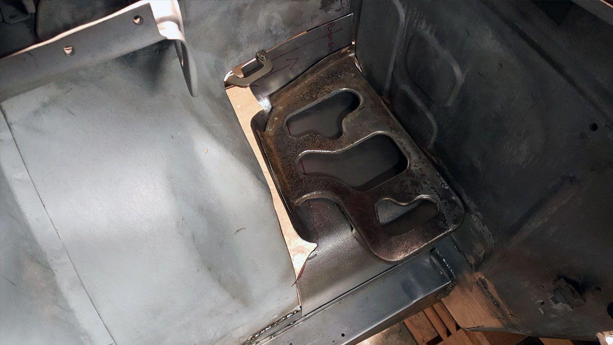
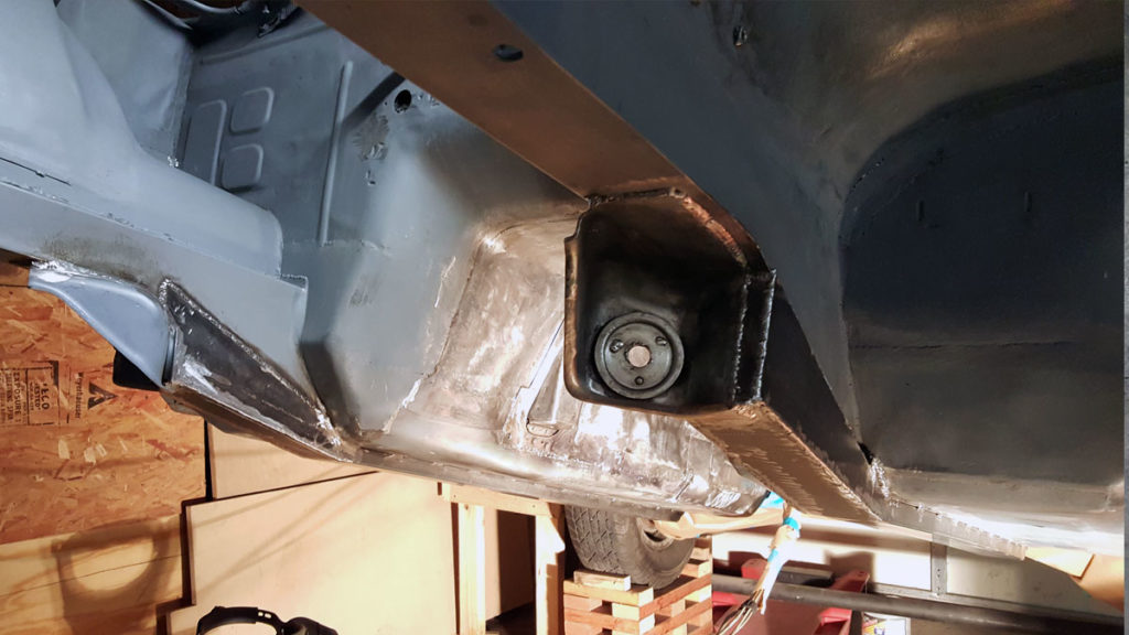
And the frame rail supports turned out great in my opinion, but I was especially pleased with the battery tray area after everything was cleaned up.

It might not be perfect, but for some guy new to sheet metal fabrication, working out of his garage… I’m happy with the results.


To find a particular page, use the search feature or index page.


17). Suspension brackets

The torsion bar brackets were going to have to be reused (another part I would think should be available aftermarket but isn’t – I don’t think) but first I had to remove them from the chunk of frame rail they were still attached to.

Aside from this being a lot of work, my method of removing them left them in need of a bunch of repair work before going back on.

First the passengers side…

Followed by the drivers side.

Which I was able to remove with drilling out the spot welds, but unfortunately had a rusted out cup where the bushing sat.

Then, I attached the suspension crossmember and proceeded to measure and remeasure several times. So much so, I created the two dimensional model below to help me make sure I was putting them in the right spot.

Click here to download this SketchUp model, but use it at your own risk. I’ve lost some files since this was drawn and can’t remember if this was the final version I made (meaning it may have mistakes).

Once I finally committed to the dimensions I’d figured out, I welded the brackets in place. Now I could move on to the next step of the project, fabricating a frame rail support.

Did I mention it was below zero at this time? And the garage I work out of, while nice and spacious, isn’t heated or insulated.


To find a particular page, use the search feature or index page.


16). Drivers frame rail

With the drivers side floor pan worked out, I began to chop away at the frame rail so I could test fit the new piece.

Not much adjustment was needed to fit the new frame rail in place and the philips head bolts you see at the bottom right of this picture, were used to temporarily hold the frame rail in place while I mocked up its location. They were the only bolts I had with the same thread and pitch as the frame rail, but happened to be extremely long. So I just used nuts as spacers instead of cutting them down.

Once I was happy with the fit and welded it in place, I cut out a new inner wheel well lower section and bent it to fit the new rail.

It too welded in place without much excitement.

Now that I had both frame rails taken care of, I could move on to other items under the front of the car but needed to be able to work under it without anything in the way. So I strapped it to the rafters and had all the room in the world.

I remember texting my dad that picture and he overreacted like most dads do, telling me I was going to bring the roof down or the car was going to crush me. I assured him that I’d shore up the front, which I did, but there was truly nothing to be worried about as the car was so light with almost everything removed. I could easily lift the front by hand.


To find a particular page, use the search feature or index page.


15). Drivers floor pan

The drivers side floor pan didn’t look nearly as bad as the passengers side, and I felt like I was more prepared for what I was in for this time around.

I was wrong.

The drivers side floor board was a nightmare to remove. Mainly because again, the preferred method by the previous fabricator was to layer sheets of steel over the rust and cover it with body filler. Only this time, it wasn’t enough to layer the inside with 18 gauge and body filler, they also used 10 gauge on the bottom where the frame rail had disintegrated. These multiple layers were giving me and my grinder a run for our money.

Eventually though, it came out.

And just like the other side, I needed to work on several little rusted out spots before I could address the real issue. But once those were taken care of, the new floor pan went in without much hassle.

The seat brackets on the other hand, they required quite a bit of reconstructing before they were fit to go back in. But eventually, they too made their way back into the car.

With that out of the way, it was time to start on the drivers side foot well. Which was fairly straightforward without a new battery tray to recreate and just required me to cut a section out of the frame rail like the passengers side, then create a new piece to weld in.

Here’s the finished product from the outside…

And the inside.

Turned out alright, don’t ya think?


To find a particular page, use the search feature or index page.


14). Battery tray

I’d be lying if I said that I wasn’t worried about rebuilding the floor pans and frame rails. But one of my biggest concerns was the battery tray area. Especially after it became this massive hole that contained several bends and complex curves that needed to be recreated.

But I approached it like the rest of the car, with ignorance and hope and began to chip away at it one bend at a time.

And for me, it helps if I write notes and draw little illustrations on the piece I’m making along with where to cut and bend. I’m a visual person and it seems to make the whole process go more smoothly.

Once I had the rough shape made, I welded it in place, then began to fill the smaller holes until it was a solid again.

Aside from it being obvious that I need to really work on my welding, I feel like it’s acceptable.


To find a particular page, use the search feature or index page.


13). Passengers frame rail

With the passengers side foot well pretty much squared away, I started to cut out the rest of the passengers side frame rail. To keep things relatively square, I created a triangle shaped frame and bolted it to the hood catch and shock towers which you can kind of see in this photo.

Below is a view from the outside of the wheel well. Which took weeks by the way, to scrape off the tar undercoating and wire wheel down to bare metal before spraying them with primer.

And if you look closely, you can make out where the wheel well had been welded, or brazed rather, to the inner fender wing. Meaning that some part of this had been replaced, probably due to an accident in the front right of the car.

When I ordered new floor pans, I also ordered a set of frame rails. They too required a bit of adjustment to get to fit, but seemed to need much less.

Between the power tools, steel tube reinforcement and trying to make sure I had enough light in the engine bay, I found myself in tight quarters, surrounded by a web of electrical cords and steel.

I had to remove a lot of steel when I removed the old frame rail. So much so, that I had to pretty much make the entire bottom from scratch.

But before I could do that, I needed to replace the suspension pockets because mine were shot. After a few failed attempts at forming one, I settled on fabricating them out of several pieces of 14 gauge, welded together.

Dimensions below and a link to the model if you want to make your own.

These pockets are commonly rusted out on S30’s and to my knowledge, they’re not available to buy, which is surprising to me. But I feel that mine came out alright.

Next it was time to figure out what I was going to do about the massive hole where the battery tray used to be.


To find a particular page, use the search feature or index.


12). Passengers foot well

Before I could move on to the passengers side frame rail, I needed to rebuild the foot well. But just like the floor board, it was completely rusted out and then covered with sheet metal and body filler, so I had to cut it all out.

And that left a huge hole that would require a ton of new steel. So I began by creating a piece that would roughly fit the opening I had cut out and worked from there.

It ain’t pretty, but it did the job.

Completed, from the other side.

And here it is after I slathered some more seam sealer over the welds.

This was still early in the build and I was trying to figure out the best way to go about sheet metal fabrication and approached it with a, “try to cover as much area with a single piece of metal” attitude. Which sort of worked but I needed to fine tune my methods.

I was also still learning the nuances of welding thin metal and it showed. My welds looked like crap and I was warping the steel in several places.


To find a particular page, use the search feature or index page.